Related parameter preview:
1. Previous article
Focal length, working distance and magnification, aperture and depth of field, field of view angle, distortion
2. Part Two
Maximum sensor size, in pupil and out pupil, total optical length, main light angle CRA, resolution, MTF curve, zoom, focusing, telecentric optical path structure, telecentric degree, camera interface (mount type)
The imaging lens is an important component of optical products, and its function is to image the target object on the image sensor. In this issue of the Light Chasing Classroom, we will continue to explain the parameters and terminology of imaging lenses, helping us better understand the performance characteristics of lenses and complete lens selection and matching for different application scenarios.
1. Maximum sensor size
As shown in the figure below, the imaging of the lens in the image plane is circular, but the sensor that receives the image is usually rectangular, so the final saved image is rectangular.
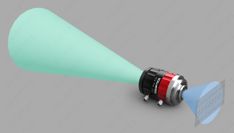
Figure 1, Circular phase surface and rectangular sensor
As an example, the lens imaging size will be designed according to the size of a universal sensor, so that the outer edge of the circular image plane coincides with the four corners of the rectangular sensor. This sensor size is the maximum sensor size of the lens (green 2/3 "sensor in the figure below). If a larger sensor (purple 1" sensor in the figure below) is used, the four corners will be outside the circular image of the lens. Using a smaller sensor (pink 1/1.8 "sensor shown below), the sensor only captures a smaller area of the circular image, resulting in a smaller field of view and angle of view.

Figure 2. Matching effect of 11mm diameter image surface with sensors of different sizes
The name expression of commonly used sensors on the market is neither the length of any side of the sensor nor the length of the diagonal, and such dimension labeling is difficult to form a specific concept of size.
The following table shows the common size specifications of general sensors in the market. The sensor with diagonal length matching the image size of the lens is the maximum sensor size of the lens.
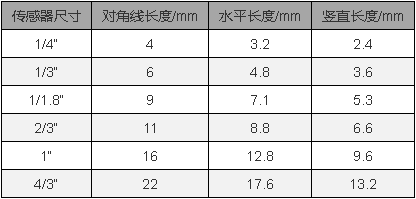
Table 1, Common General Sensors
2. Exit pupil, entrance pupil and aperture diaphragm
Exit pupil: The exit pupil is the effective aperture that limits the outgoing beam of light, and is the image formed by the aperture aperture aperture by the rear optical system; The exit distance is the distance between the exit pupil and the last surface of the lens; The exit pupil diameter is the size of the image formed by the aperture diaphragm on the rear optical system.
Entering the pupil: The entering pupil is the effective aperture that limits the incident beam of light, and is the image formed by the aperture aperture aperture by the forward optical system; The entering pupil distance is the distance between the entering pupil and the surface of the first lens of the lens; The diameter of the pupil is the size of the image formed by the aperture diaphragm on the optical system ahead.
Aperture aperture: Any aperture screen or lens frame in the optical path that can limit the beam of light can be called an aperture, and the aperture that ultimately limits the size of the incident beam in the optical path is called an aperture aperture.
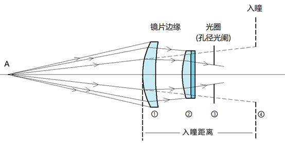
Figure 3, pupil entry, pupil distance, aperture diaphragm
Taking the optical path shown above as an example, the edges of lenses 1 and 2, as well as the aperture of 3, can limit the incident beam. Only a portion of the beam that can pass through lens 1 can enter lens 2, while only a portion of the beam that passes through lens 2 can enter aperture 3. Therefore, aperture 3 ultimately limits the size of the beam that can enter the lens head for imaging, which is the aperture aperture of this optical path. When observing at point A, aperture 3 is magnified into a virtual image of aperture 4 by lenses 1 and 2. The light emitted from point A enters aperture 3 through lenses 1 and 2, which is equivalent to light entering aperture 4 directly from point A. The fourth image formed by the aperture of two lenses is called the entrance pupil, and the distance between the entrance pupil and the first lens of the lens is the entrance pupil distance.
3. MTF curve and resolution
The resolution of a lens refers to its ability to distinguish two nearby points, also known as resolution. The lens resolution is usually characterized by MTF curves.
The MTF curve represents the relationship between spatial frequency and transfer function values. The horizontal axis represents the spatial frequency, which is the logarithm of lines per mm, and can represent the degree of proximity between two points. The vertical axis represents the transfer function representing contrast, with a value of 1. The contrast between the lines is obvious and can be clearly distinguished; The value is 0, and the line pairs cannot be distinguished without contrast.
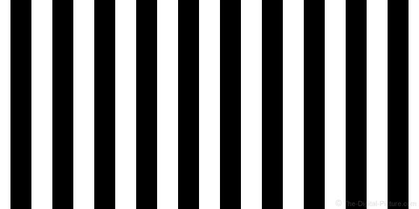

Figure 4, images with contrast ratios of 1 and 0.6 for line pairs
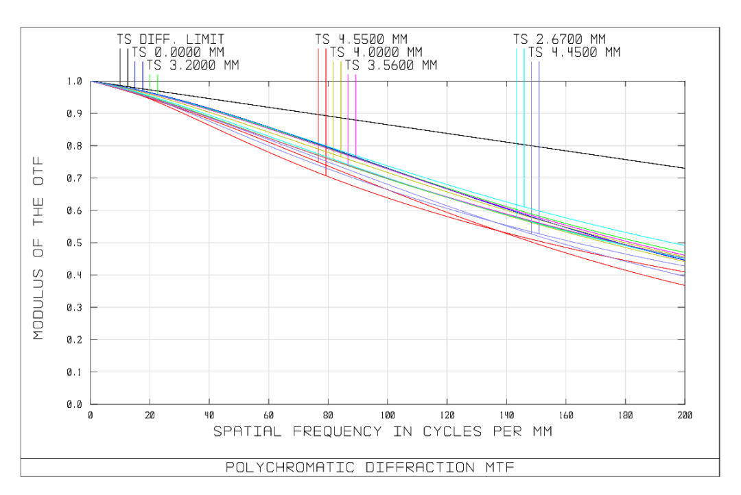
Figure 5, MTF curve of a certain model of lens
There are multiple curves in Figure 5, and each curve is labeled as high. 0mm represents the MTF value on the axis, and 4.5mm represents the MTF value with an external image height of 4.5mm. The MTF curves with different image heights have high consistency and non dispersion, indicating high on-axis and off axis consistency of the lens. The black line represents the MTF value limited by physical limits.
The sensor resolution generally refers to the product of the number of horizontal and vertical pixels, such as 5 million pixels, and the number of horizontal and vertical pixels of the sensor is 2560 x 1920. The size of a single pixel corresponds to the size and resolution of the sensor. The pixel size can be obtained by dividing the sensor size by the number of pixels according to Table 1. Like 2/3 "5 million sensor, pixel size 3.4 μ M. The resolution of the lens should match the pixel size. Usually, pixel size is selected based on half the size of the line pair.
Taking the 1/1.8 "small pixel lens as an example, it has a high-resolution design of 230lp/mm and a pair size of 1000/230 μ M=4.34 μ m. Matching pixel size is 4.24/2 μ M=2.17 μ m. Can match 2.2 on the market μ The sensor of m. Selection ratio 2.2 μ Small pixels do not bring richer details.
4. Main light angle
The Chief Ray Angle (CRA) of the lens represents the angle between the main ray of the lens and the optical axis. The main light is the light emitted from the observed object, passing through the center of the aperture aperture, to the imaging point.
The main light angle CRA of the sensor represents the maximum angle at which light can be focused on a pixel. Beams exceeding this angle cannot be fully received by the sensor. Generally, it is required that the lens CRA is not greater than the camera sensor CRA.
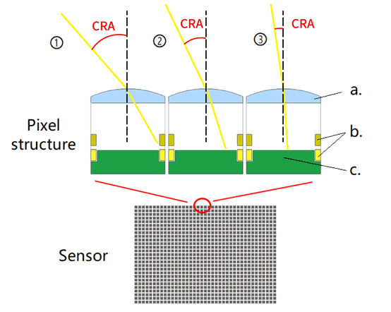
Figure 6, Sensor main light angle
a. Focusing lens above the pixel, b. metal wire, c. photoelectric conversion area.
The main light angle of ray 1 in the picture exceeds the sensor CRA, and the light cannot reach the photoelectric conversion area; The main light angle of No. 2 and No. 3 is smaller than the sensor CRA, and the light can reach the photoelectric conversion area.
5. Telecentric optical path structure and telecentric degree
There are three types of structures in the telecentric optical path: the object side telecentric, the image side telecentric, and the double telecentric.
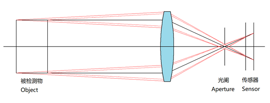
Figure 7, Object Far Center Optical Path
The aperture aperture is located on the focal plane of the image, and the main rays entering the lens pass through the focal point of the image at the center of the aperture. In the object side, these main rays are parallel to the optical axis. Only light rays parallel to the optical axis can pass through the aperture, and the distance between the measured object and the lens is consistent in imaging size.
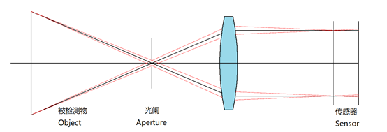
Figure 8, Image Far Center Optical Path
The aperture aperture is located on the focal plane of the object, and the main rays entering the lens pass through the focal point of the object at the center of the aperture. In the image, these main rays are parallel to the optical axis. The light passing through the aperture is parallel to the optical axis when passing through the lens, and the distance between the sensor and the lens does not affect the imaging size.

Figure 9, dual telecentric optical path
The plane where the aperture is located is both the object focal plane and the image focal plane. The main light of the object and the main light of the image are both parallel to the optical axis.
Telecentricity: The angle at which the main beam of the telecentric lens deviates from the optical axis. The smaller the angle, the better the telecentricity, the smaller the magnification error of the imaging, and the more accurate the measurement.
6. Checkpoint
Mainstream industrial lenses generally use C-mount, with a mount thread of M25.4x0.8
Please refer to the table below for specific names, corresponding flange distances, and thread sizes:
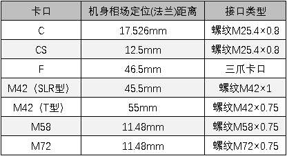
Table 2: Common lens mount specifications
7. Total optical length
The distance from the surface of the first lens to the image plane is the total optical length of the lens.
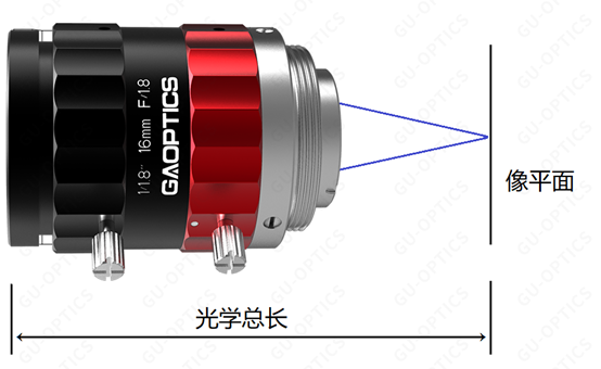 Figure 10, Schematic diagram of total optical length
8. Focusing and Zooming
When using a fixed focus lens, what is commonly referred to as focusing is actually focusing. The focal length of a fixed focus lens is fixed and unchanged. When changing the working distance, manually adjust the lens focus ring to make the image clear.
When it is inconvenient to control the imaging size by changing the working distance, you can replace the lens with another focal length or use a zoom lens. A zoom lens has an additional zoom ring than a fixed focus lens. Rotating the zoom ring can change the field of view angle, and the size of the image can be changed when the working distance remains unchanged.
The above is an explanation of the parameter terms for imaging lenses, which basically covers various professional terms related to lenses that can be encountered in daily work. In the following article, we will introduce various parameter terminology and graphic explanations of optical components to readers. Stay tuned.
Special statement: The above content is sourced from "United Optics Technology". If there is any infringement, please contact us to delete it!


